For full functionality of this site it is necessary to enable JavaScript.

Keysight P-Series Power Meters

**Designed For Today’s Demanding Applications** Today’s complex electronic devices have stringent power requirements. Keysight Technologies, Inc. P-Series po

Designed For Today’s Demanding Applications

Today’s complex electronic devices have stringent power requirements. Keysight Technologies, Inc. P-Series power meters and sensors deliver the wide bandwidth and high-performance measurements that you need to be confident that your products are meeting their power specifications.

The P-Series power meters have a 30 MHz video bandwidth and 100 M-sample/s continuous sampling rate for fast, accurate, and repeatable power measurements. When these meters are used with the P-Series wideband power sensors, they provide up to 40 GHz frequency coverage, a wide dynamic range, and extensive measurement capability that has been optimized for aerospace/defense, wireless communication, and wireless networking (IEEE 802.11a/b/g) applications.

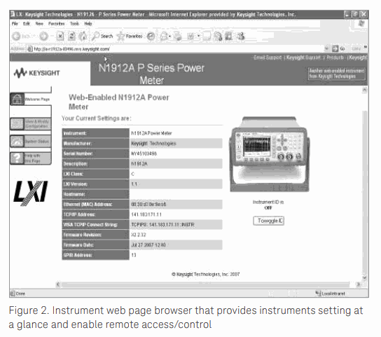
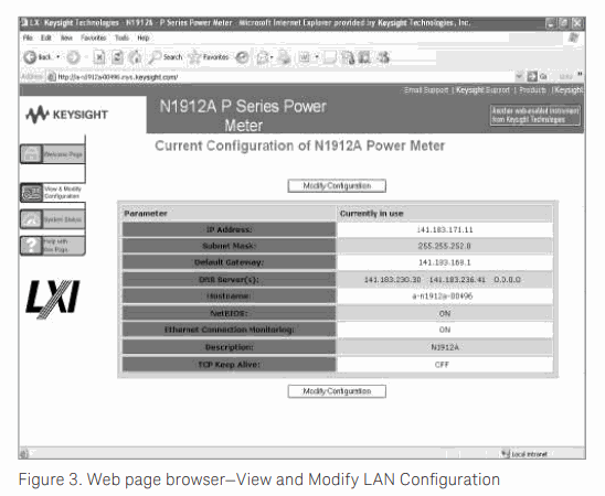
The P-Series power meters are now LXI (LAN eXtensions for Instrumentation) Class-C compliant instrument which combines the advantages of Ethernet with simplicity and familiarity of GPIB. This helps the test systems designers and integrators to create faster and more efficient systems. With the power of ethernet, the P-Series power meters reduce the time needed to set up, configure and debug test systems.

Packed with capability
When you choose the P-Series power meters and sensors, you get best-in-class pulse analysis and peak power measurement specifications.
A high-performance, 14-bit, 100 M-sample/s measurement engine drives the P-Series power meters, so you can capture single-shot as well as repetitive events over a wide bandwidth. For applications such as radar testing that require accurate pulse measurements, the power meter, and sensor combination has ≤ 13 ns warranted rise and fall time performance.
With up to 30 MHz of video bandwidth, the P-Series gives you a single-instrument solution for testing wide bandwidth products such as the multi-carrier power amplifiers used in the newest wireless base stations.
Bandwidth flatness is corrected to 0.1 dB over the 30 MHz bandwidth for highly accurate peak power measurements.

Comprehensive power, time, and statistical measurements
The P-Series power meters and sensors offer comprehensive measurements that satisfy the requirements of many power applications in R&D and manufacturing.
– Peak power, min power, average power, and peak-to-average ratio power measurements
– Time-gated and free-run measurement modes
– Automatic rise time, fall time, pulse width, pulse period, duty cycle, time to positive occurrence, and time to negative occurrence time measurements
– Autoscale and auto gate of pulse
– Complementary cumulative distribution function (CCDF) statistics PC-based measurement software (N1918A)2 adds even more pulse-parameter and statistical analysis capability, for performance approaching that of a traditional peak power analyzer.

Flexible configuration
With the P-Series products, you can choose a configuration that’s right for your application:
- P-Series power meters:
N1911A single-channel power meter, 9 kHz to 110 GHz (sensor-dependent)
N1912A dual-channel power meter, 9 kHz to 110 GHz (sensor-dependent)
- P-Series power sensors:
N1921A wideband power sensor, 50 MHz to 18 GHz
N1922A wideband power sensor, 50 MHz to 40 GHz
The P-Series power meters are also compatible with all 8480 Series, E-Series, and N8480 Series sensors.

External calibration-free measurements
The P-Series power sensors are the first to provide “internal zero and calibration” which eliminates the need for sensor calibration using an external reference source. Keysight’s patent-pending technology (see Figure 1) integrates a dc reference source and switching circuits into each power sensor so that you can zero and calibrate the sensor while it is connected to a device under test. This feature removes the need for connection and disconnection from the calibration source, thereby reducing test times, measurement uncertainty, and wear and tear on connectors. It is especially useful in manufacturing and automated test environments where every second and every connection counts. Sensors can be embedded within test fixtures without the need to switch in reference signals.

Simplified correction factors
To ensure the accuracy of power measurements, a power meter typically overlays many different sensor correction factors including linearity, frequency, and temperature. At higher bandwidths, this technique can become cumbersome and less than accurate.

To simplify the process and improve measurement speed while preserving measurement accuracy, the P-Series uses a four-dimensional (4-D) modeling technique that measures input power, frequency, temperature, and output voltage across the power sensor’s specified measurement ranges. Data from this 4-D model is generated during Keysight’s initial factory calibration of the sensor and stored in EEPROM. Advanced algorithms are used to quickly and accurately evaluate the sensors against this model, without requiring the power meter to interpolate the calibration factors and linearity curves. If you run tests in which the frequency changes often, e.g. testing multi-carrier amplifiers on different bands, you’ll notice a marked improvement in measurement speed.

Compatibility with more than 30 Keysight sensors
The P-Series power meters also work with the Keysight 8480 Series, E-Series, and N8480 Series power sensors. This gives you a selection of more than 30 sensors for power measurements over a wide dynamic range from –70 to +44 dBm, with frequency coverage of 9 kHz to 110 GHz.


Designed for Test Standardization and Interoperability
The P-Series power meters enables fast, efficient, and cost-effective creation. It also enables the reconfiguration of test systems with proven and widely used standards such as Ethernet, Web browsers, and IVI drivers. The codes are transferable/reusable from the design and development industry to manufacturing. Best of all, the same test system software can be leveraged across industries such as Research and Development (R&D), design validation, manufacturing, and services. By using the same software, test development time can be cut down significantly for new products to be marketed earlier. It also helps to provide more consistent results from development to production and prevent time wasted in correlating measurement results and finding the cause of differences. The use of industry-standard drivers such as IVI drivers enables users to use any programming languages that they are familiar with. Therefore, it is hassle-free and effective when P-Series power meters are used during instrument communications.

Enable Remote Control/Access of the Instrument
Set up of power meter is possible through an informative instrument page where you can access with a standard web browser. This page contains key information such as the manufacturer, model number, serial number, description, hostname, MAC address, and IP address. Hence, you are able to change the parameters by typing the instrument’s IP address in the Web browser. Access to test data is also possible with the power meter built-in front panel.


Simplified test set up

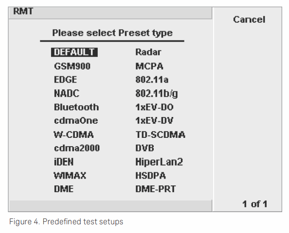
The P-Series meters are loaded with time-saving features. Predefined test setups for common measurements (see Figure 2) used in radar and wireless communication applications get you started testing, and an easy-to-use menu structure lets you step quickly through measurement sequences.


Once you have started measuring, it’s easier to fine-tune and save the setup for your unique requirements.

With an auto-pulse detect(1) capability, the power meter can automatically trigger from an unknown input signal to display the entire pulse envelope and you’re ready to begin making measurements.

Internal triggering is exceptionally stable in the P-Series meters. Versatile time-gating features include four independent measurement gates. An external triggering capability lets you synchronize your measurements to an external signal, so the power meters can adapt to a wide range of input signal levels to accommodate many different types of incoming signals.

The high-resolution, color display has a graphical user interface with multiple markers and marker functions for easy manual measurements. An IVI-COM driver for the P-Series power meters and sensors facilitates programming in Keysight VEE, LabView, Labwindows, C, C++, and MATLAB environments.

Convenience and security
Keysight’s IO Libraries Suite ships with the P-Series power meters to help you quickly establish an error-free connection between your PC and instruments regardless of the vendor. It provides robust instrument control and works with the software development environment you choose.
LAN, USB, and GPIB connectivity are standard in every P-Series power meter to accommodate the majority of modern interfaces.

Backward compatibility of the P-Series meters with Keysight's current offering of power sensors gives you numerous options for extending the usefulness of your Keysight power measurement tools. Identical features and measurements performed by the EPM, EPM-P, and P-Series power meters are code compatible, having the same SCPI commands,

A 2-year calibration cycle on the P-Series power meters helps reduce the cost of ownership.

A universal line input lets you plug into a supply voltage just about anywhere without any additional hardware or adjustments, and multiple sensor cable length options (1.5 m, 3 m, and 10 m) make it easy to reach out-of-the-way devices in a variety of test environments.

Save your display information using PC and SCPI commands. Screen dumps can be downloaded to a PC in the form of a bit-map. Power versus time trace displays can also be downloaded for further processing or for hardcopy printouts for your log book or your company literature.

Secure mode protects sensitive data by erasing from instrument memory all user parameters, including save/recall states and power on last states.

Optimized for Radar Testing

Multifunctional radar system testing | Rohde & Schwarz

If you design or manufacture components and subcomponents for radar systems, you need a way to accurately measure the output power and timing parameters of the radar pulses. The P-Series power meters and sensors provide a cost-effective peak and average power solution that is ideal for the task.

With warranted performance that includes up to 40 GHz frequency range, a 30 MHz bandwidth, and ≤ 13 ns rise and fall time, the P-Series covers most of today’s high-frequency radar test applications.

Ideal in the lab and manufacturing

In the lab or on the manufacturing floor, you can use the P-Series power meters and sensors to check that pulses in radar transmit or receive modules conform to a specified amplitude and shape. You can focus your measurements on a single pulse or on a train of hundreds or even thousands of pulses. Use real-time markers and other features to help you determine whether the pulse power is degrading or the pulse shape is changing over time.


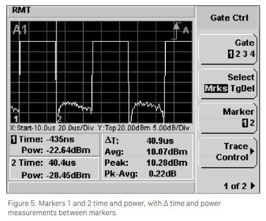
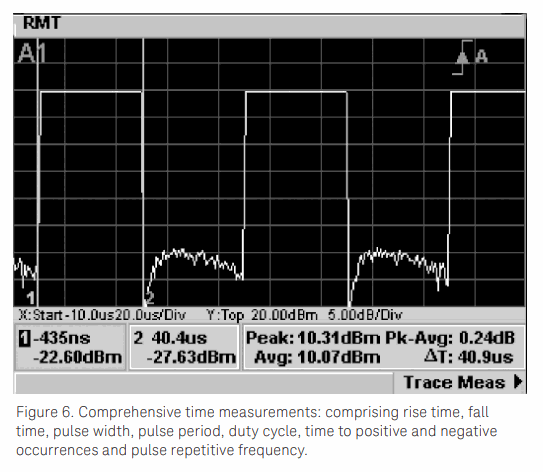
Comprehensive measurements are built-in: peak, average, peak-to-average ratio, time, and instantaneous power at markers 1 and 2 (see Figure 3), time measurements comprising rise time, fall time, pulse width, pulse period, duty cycle, time to positive occurrence, time to negative occurrence and pulse repetitive frequency (see Figure 4). While the power meter and sensor combination make an excellent standalone power measurement system, the drivers included in the system make it easy to integrate into other systems in an ATE environment.

Measure the time delay between your trigger event and the pulse envelope
Automatic measurement of the time to positive occurrence allows you to verify the delay time between the trigger event using the pulse modulator to drive the power meter’s external trigger and the RF output of your transmitter.

Remote capture of up to 10 pulses

For ATE applications, using SCPI commands, you can automatically measure the important time parameters of pulse duration, separation, and period on the capture of up to 10 pulses.

Alternative to a peak power analysis system
By providing comprehensive, accurate, and repeatable power measurements in a small form factor that is well-suited for R&D and manufacturing test, the P-Series power meters and sensors are a viable alternative to a peak power analysis system and at an attractive price point.


Optimized for Multi-channel Power Amplifier (MCPA) Testing

MPA Series Multi-Channel Amplifiers

The base stations that support today’s high-capacity wireless networks must handle a growing number of data channels. Rather than incorporate a separate amplifier for each channel in the system, engineers are streamlining their designs by using multi-channel power amplifiers (MCPAs). If you are designing or manufacturing MCPAs, you need a wide bandwidth tool that can measure the peak and average power or peak-to-average ratio to verify that your product does not exceed maximum power specifications. The P-Series power meters and sensors offer a complete power measurement solution with a 30 MHz bandwidth. It can measure peak and average power of up to six 3G (5 MHz) carriers over a wide –35 to +20 dBm dynamic range, more than enough for power amplifier testing today and in the future.

Accurate power measurements
The accuracy of power measurements is a major concern in high data rate wireless applications. With the P-Series products, you can accurately measure the linearity of power amplifiers (input power versus output power) at the 1 dB compression point.

The P-Series flat video bandwidth helps to ensure the accuracy of your peak and peak-to-average ratio power measurements. Keysight characterizes the P-Series sensors over their specified temperature, frequency, and power ranges. These correction factors are stored in EEPROM, so that along with an average power measurement accuracy specification of ≤ ±0.2 dB (refer to Data Sheet 5989-2471EN) you don’t have to worry about the effects of error on your measurement.

Multi-level, TDMA power testing made easy

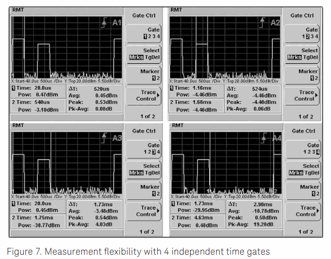
The P-Series power meters provide four independent time gates (A1-A4) in a single measurement setup (see Figure 5) so you can choose where you locate your measurements of peak, average, and peak-to-average ratio on the trace. 


Optimized for Wireless LAN Testing

Best 25 WiFi Tools for Analysis, Security, and Monitoring Wireless APs!

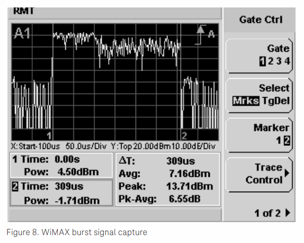
If you are designing wireless LAN (IEEE 802.11a/b/g) or WiMAX (802.16e) components and subsystems, you will need to analyze burst signals. With 30 MHz of video bandwidth, the P-Series power meters and sensors can capture signal bursts and measure the peak-to-average ratio of the transmitted power in your WLAN or WiMAX products.

You can verify the power profile and output power of WLAN components easily with the P-Series solution. For example, because the length of a wireless LAN burst is unpredictable, it is affected by the type of data being transmitted and the data rates you are trying to achieve. The P-Series power meter has an auto-pulse detect1 feature that enables it to automatically capture bursts of varying lengths, even when you do not know the parameters of the signal.

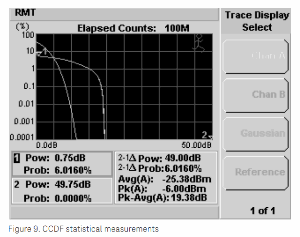
By measuring the signal’s rise time and checking the burst profile, you can identify any power transitions that could cause interoperability problems. Measuring the peak-to-average ratio and CCDF enable you to verify that a power amplifier isn’t clipping.

The preconfigured presets for WLAN and WiMAX allow easier capture of burst signals so you can get started on your measurements sooner.


Versatile for R&D and manufacturing

The P-Series power meters and sensors can measure all IEEE 802.11 WLAN signals. They can be used in developing HiperLAN and HomeRF network devices as well.

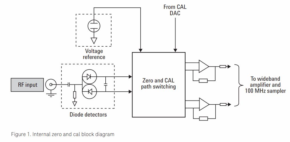
In component manufacturing, time is always money. This is true in the high volume production of wireless network devices and products where fast measurement speed is essential to maximize throughput. Minutes can be shaved from overall test times by combining the internal zero and calibration capability with the fast measurement speeds achieved through your choice of I/O interface (LAN, USB, and GPIB) for data transfer.

Capable and easy-to-use 


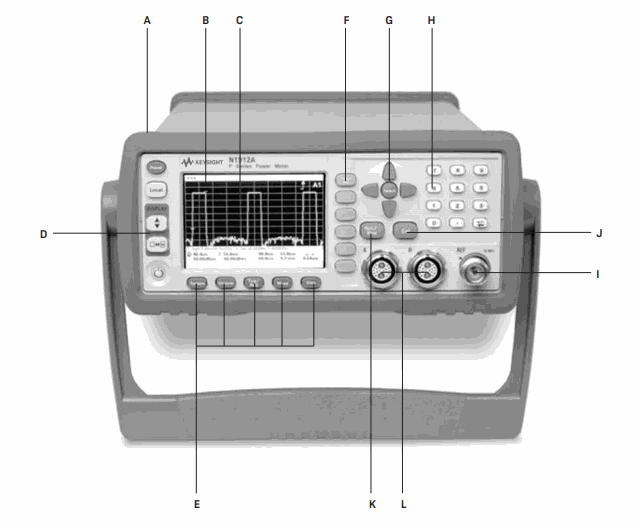
A - Half-rack width, 2 U height makes this instrument ideally sized for automated test environments.

B - Large, high-resolution color LCD has back-lighting that provides a wide angle for viewing the displayed data.

C - Full-screen graphical display has three display modes: power versus time, numeric readout, and pseudo-analog display.

D - Display keys let you select the display format for the active window, either single or split-screen formats. Two horizontal windows show the trace display (power versus time) in several formats, a large 1- or 4-line numeric display or an analog display.

E - Hardkeys provide access to the most frequently used functions, such as Trigger and Acquisition.

F - Softkey menus have been simplified so that you can more readily configure the meter to meet your specific measurement needs.

G - Arrow keys and Select allow positioning of the cursor for character selection and editing.
H - Numeric keypad makes data entry easier.
I - 0 dBm, 50 MHz power reference connector is used for power sensor calibration traceable to national standards. Typically the power meter’s 0 dBm, 50 MHz reference is used to calibrate the 8480 Series, E-Series or N8480 Series sensors when they are used with the P-Series meters. (The P-Series sensors have internal zero and calibration and thus do not require calibration with the reference source.)
J - Cal enables fully automatic digital zeroing, corrected for residual offsets, and fully automatic sensor calibration.
K - Run/Stop enables single-shot measurements.
L - Sensor connectors for attaching the P-Series sensor dual coaxial cables allow the P-Series power meters and sensors to achieve the best wideband specifications. Adapter cables N1917A/B/C are used to connect the 8480 Series, E-Series, and N8480 Series power sensors to the P-Series power meter.

Rear-panel Features


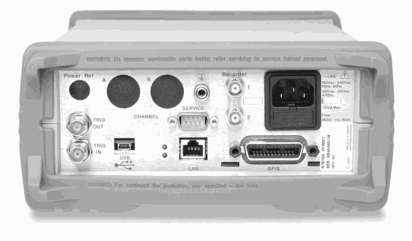
– USB 2.0, Ethernet (LAN), and GPIB connections are standard.

– Rear-panel sensor and 0 dBm Power Ref connectors, replacing the front-panel connectors, are an option (option 003) that makes it easy to incorporate the P-Series meters into a rack for automated testing.

– Trig In accepts a TTL signal for initiating measurements.

– Trig Out outputs a TTL signal for synchronizing with external equipment.

– DC Recorder output, 0 to 1 volt. The N1912A has two recorder outputs as shown.

– Ground connector is available for those applications that require a hard-wired connection between the power meter’s ground and common ground.

– Line power is provided by a universal input voltage range.


注册收新闻 - 获得优惠活动的机会